Image Alignment 1
by minimizing loss (Brute Force approach)
Given a grayscale image consisting of three channel images (R, G, B), the goal is to extract each channel image and align these images to form a single, properly colorized image.

Mathematical Formulation of the Alignment Procedure
Given a gray scale image \(I\) consisting of three channel images \(\{I_R, I_G, I_B\} \in \mathbb{R}^{H \times W}\), corresponding to the Red, Green, and Blue channels of a color image, where \(H\) is height, \(W\) is width, the goal is to extract each channel image and align these images to form a single, properly colorized image \(I_{RGB} \in \mathbb{R}^{3 \times H \times W}\), where 3 is the number of channels of an image. The challenge is to find the optimal displacement vectors \((dx_R, dy_R)\), \((dx_G, dy_G)\), and \((dx_B, dy_B)\) that align the channels such that visual artifacts are minimized. Details are illustrated below.
Procedures
The following steps outline the procedure to align the color channels:
1. Preprocessing the Images
- Remove the white borders to isolate the main content of each channel.
- Divide the input image into three parts, corresponding to the three color channels.
2. Pair Alignment
- Choose one of the channels (e.g., Green channel) as the reference.
- Crop the outer part and use the middle part of each channel to compute the pair alignment for the other two channels (e.g., Red and Blue) relative to the reference channel using one of the defined metrics (MSE, NCC, SSIM), within the defined search window.
From now on, the explanations assume the reference color as Green, and the other two channels as Red and Blue.
3. Optimization
- Using the Brute Force algorithm, exhaustively search for the displacement vectors \((dx_R, dy_R)\) and \((dx_B, dy_B)\) within the search window \([-15, 15]\) that minimize the align metric.
- Evaluate the alignment cost function for each possible displacement within the window.
- Select the displacement vector that yields the minimum cost as the optimal alignment.
The displacement vector for the reference color is \((dx_G, dy_G) = (0, 0)\).
4. Final Alignment
- Apply the displacements to the uncropped respective channels and merge the aligned channels together to produce the final RGB image \(I_{RGB}\).
Alignment Costs
We define \(D(I_{\text{ref}}, I_{shift})\) as the alignment cost function, where \(I_{\text{ref}}\) is the reference channel image and \(I_{shift}\) is the shifted channel image. (e.g., \(I_{\text{ref}} = I_G, I_{shift} = I_C(x + dx_C, y + dy_C)\) where \(C = \{R, B\}\)). There are three alignment costs to consider:
- Mean Squared Error (MSE)
- Normalized Cross-Correlation (NCC)
(Negative NCC is implemented) - Structural Similarity Index (SSIM)
Lower value represents better alignment within each metric.
Optimization Problem
The goal is to find the displacement vectors \(d_C = (dx_C, dy_C)\) that minimize the cost function:
\[\arg \min_{d_C} D(I_{\text{ref}}, I_{shift})\]Constraints
Search Window:
To limit the computational cost, the search for \(dx\) and \(dy\) is restricted to a finite window of pixel size 15, in both \(x\) and \(y\) directions:
\[-15 \leq dx_C, dy_C \leq 15, \text{ for } C \in \{R, B\}.\]Description of Implementation
Preprocessing the Images
To remove the white boundary from an image, I first calculated the row and column means of the pixel values. Since white areas have high values (close to 1) and black areas have low values (close to 0), I enhanced the contrast by cubing the mean values. This exaggeration made it easier to distinguish the boundary. I then cropped the image by selecting the indices where the mean values dropped below 0.1, effectively removing the white boundary. After identifying the boundaries, I divided the image into three equal parts by splitting its height into three sections.
Cropping the Outer Parts
To ensure an accurate comparison between the image channels, I first cropped the outer part of each channel to focus on the main area, which is the central part of the images. This strategy not only improved the alignment but also significantly reduced the execution time, as it reduced the amount of pixels to be padded.
I experimented with different sizes for the cropped section: 100 × 100, 200 × 200, and the full (uncropped) image. Initially, I thought optimizing the uncropped image would lead to poor alignment because the cost calculation would include the black frame pixels and would increase the gap when the black boundary and non-black boundary meet. However, the alignment turned out better than I expected. That said, the execution time for the uncropped image was significantly longer. I believe the difference in execution time is due to the varying number of pixels being optimized.
Effect of Metrics
Alignment Quality
When the reference color was green and the order of channel alignment is RGB, it was not distinguishable which metric performs better in optimization because every metric worked out well. However, the difference showed up when the reference color changed. Overall, MSE proved to be the least effective alignment metric, likely due to its sensitivity to outliers. In contrast, SSIM delivered the best performance, as it focuses on structural similarity rather than pixel-wise differences, making it more robust for alignment tasks.
Speed of Computation
It turned out that MSE took the least time, followed by NCC, with only a small difference in execution times between the two. However, SSIM took significantly longer to optimize in comparison, indicating that it is computationally more expensive. This is likely due to the more complex nature of SSIM, which evaluates structural information in the images, compared to MSE and NCC, which focus on pixel-based differences and normalized correlations respectively.
Colorized Outputs
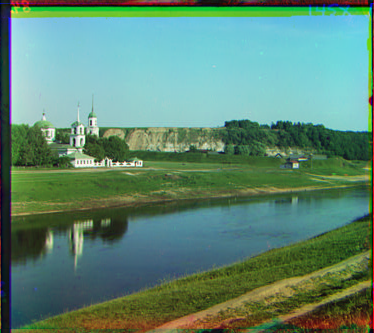
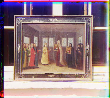
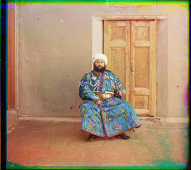
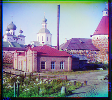
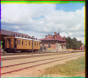
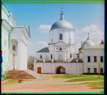
The results are aligned using SSIM metric.
Check out the code here!